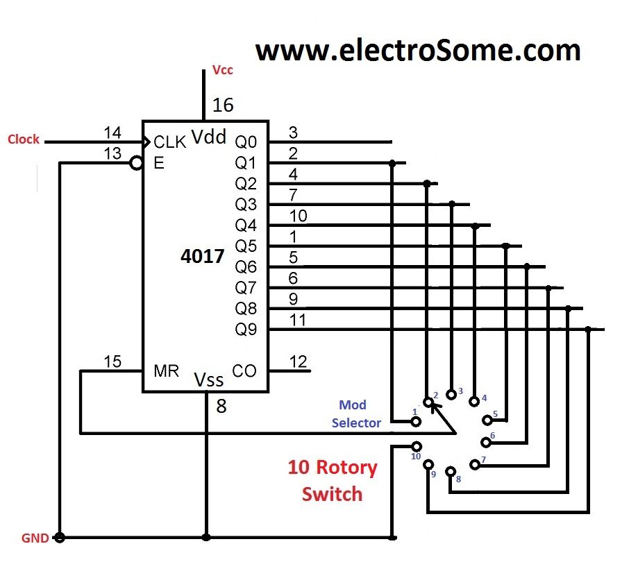
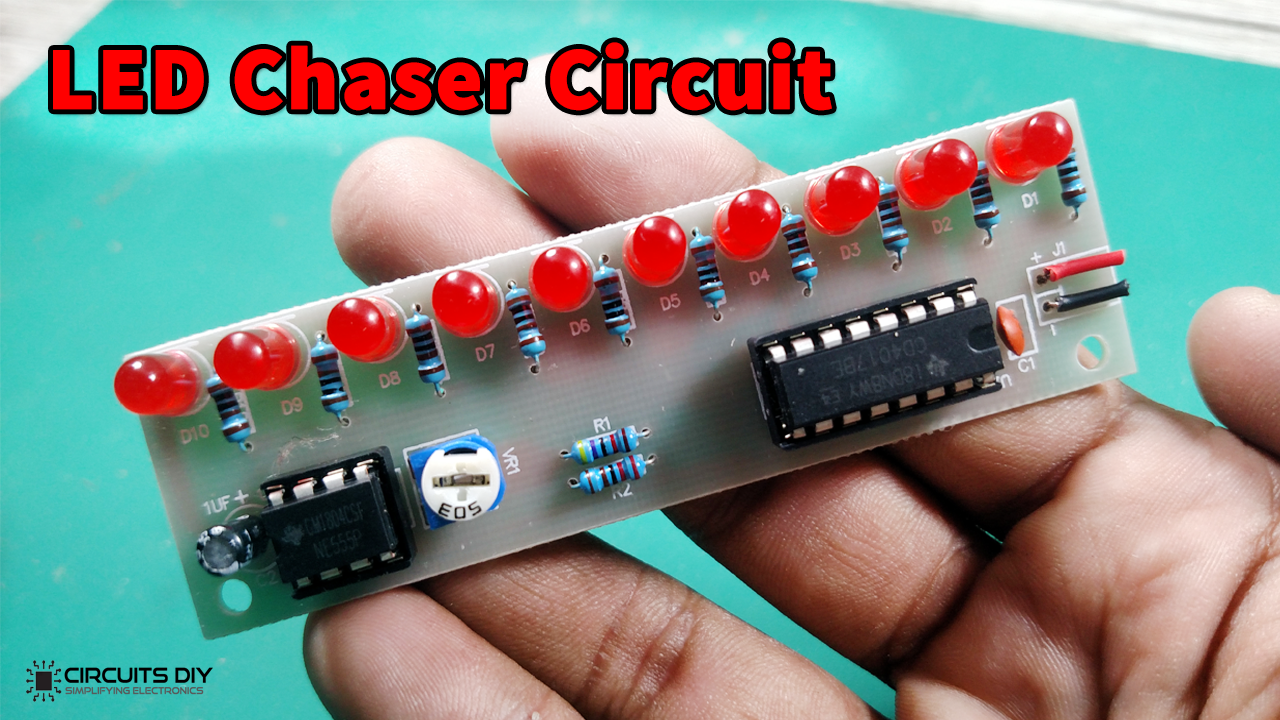
LED Chaser using 4017 Counter and 555 Timer
Each light emitting diode (called a segment) is illuminated using an electrical current, and by illuminating various combinations of segments so that some segments will be turned "ON" and emitting light while others will be turned "OFF" we can display individual characters or numbers.

LED frequency counter
The so-called chaser or sequencer is one of the most popular types of LED-driving circuit and is widely used in advertising displays and in running-light 'rope' displays in small discos, etc.
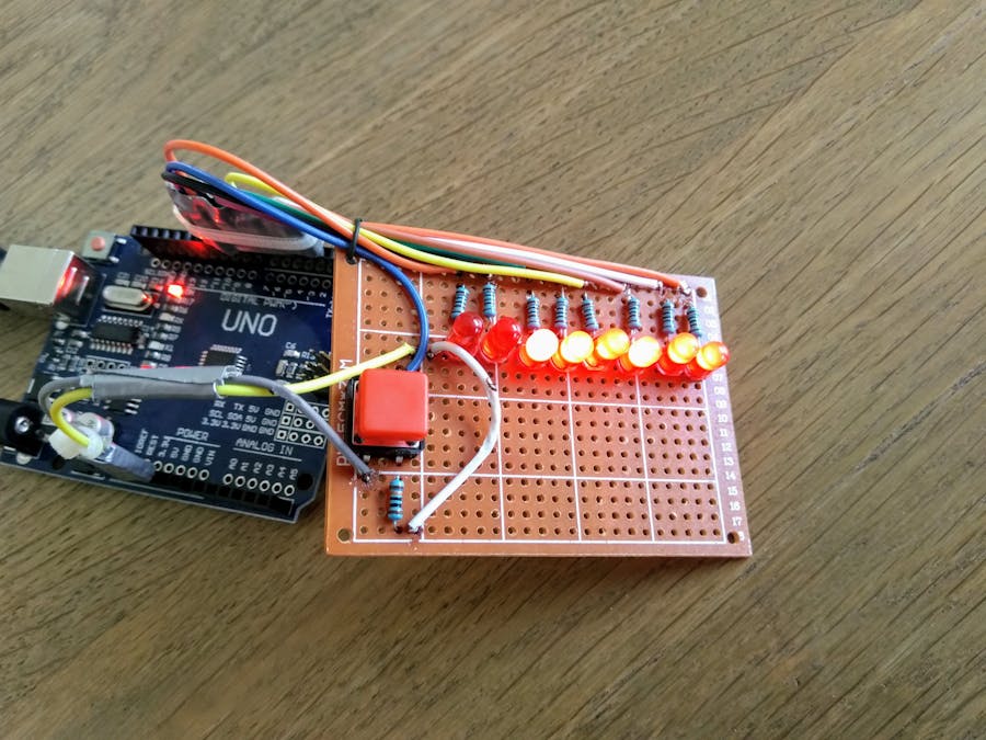
8Bit LED counter Arduino Project Hub
In this project, you will construct the automated sequencing light-emitting diode (LED) output circuit, illustrated in Figure 1. Figure 1. Automated 10-bit counter with sequencing LED bar graph outputs. You will also use this circuit to design a frequency divider and a switch debouncing circuit.
LED frequency counter
Our application-optimized products and expert design assistance ensure the best possible performance for your design. Cree LED holds more than 4000 LED patents and though we lead the industry in performance, we never stop innovating. Our products are built on scalable architectures that enable design upgrades with "drop-in" improvements.
Digital Counter Circuit Diagram IOT Wiring Diagram
In an LED chaser circuit, the 555 timer is configured as an astable oscillator, which means that it will generate a continuous stream of pulses. The frequency of the pulses can be adjusted by changing the values of the resistors and capacitors that are connected to the timer IC. The pulses generated by the 555 timer are then used to control a.
14+ 5 Led Chaser Circuit Using Transistor Robhosking Diagram
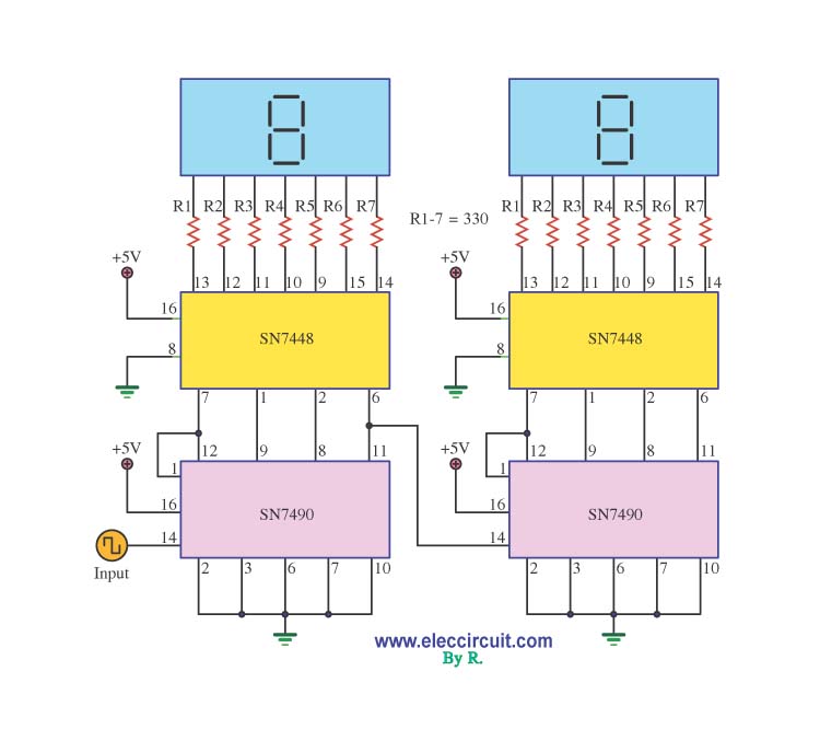
R1-R7 470 Ohm 1/4 Watt Resistor U1 74LS90 TTL BCD Counter IC or 7490,74HC90 U2 74LS47 TTL Seven Segment Display Driver IC or 7447,74HC47 DISP1 Common Anode 7 Segment LED Display
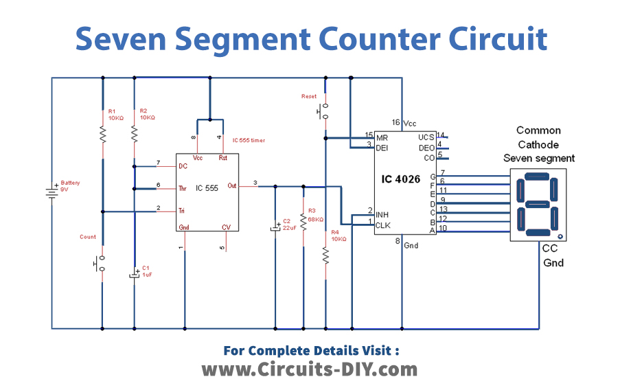
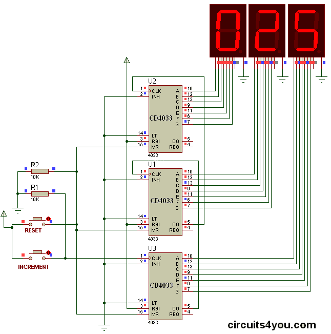
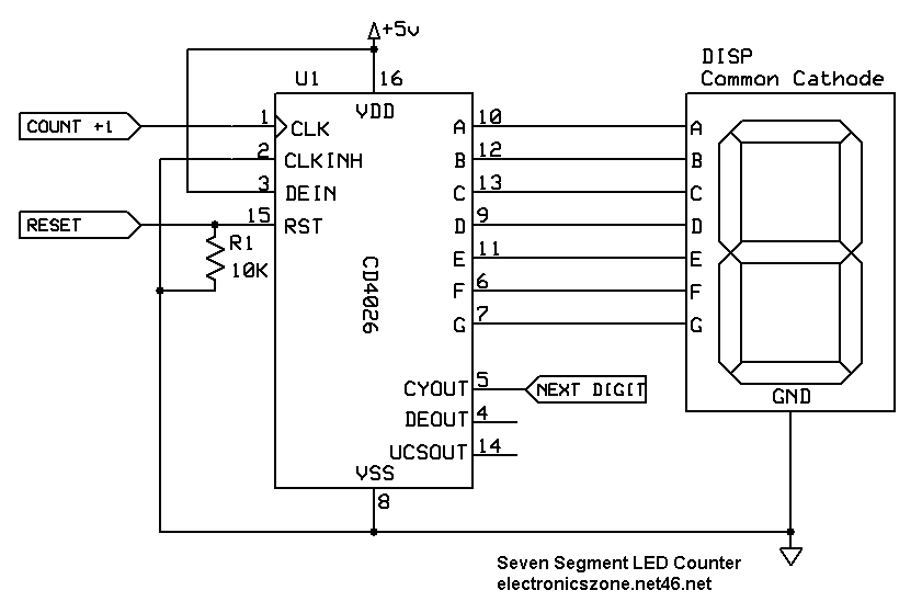
Simple Seven Segment Counter Circuit using CD4026
Introduction. In this tutorial, we will create a simple Counter With LED Matrix | Arduino Project, counter using an Arduino UNO and two 8×8 Dot Matrix MAX7219 modules. The counter will increment or decrement based on the input from a push button. The MAX7219 modules will display the count using LED matrices, making it visually appealing and.
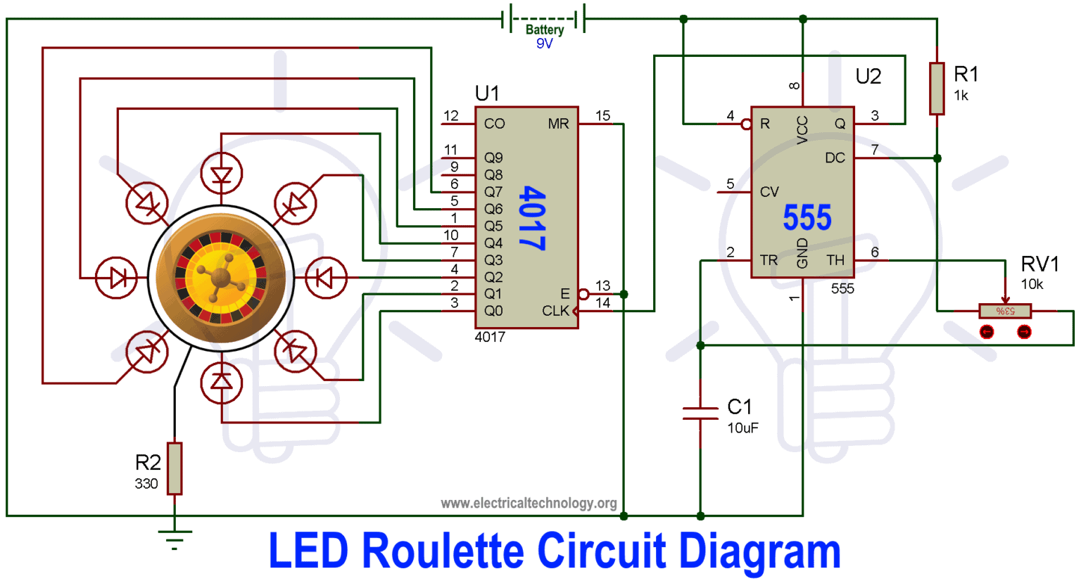
LED Roulette Circuit Diagram using 555 Timer IC & 4017 Counter
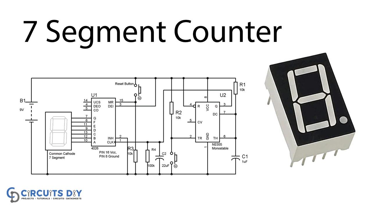
Description Here is the circuit diagram of a seven segment counter based on the counter IC CD 4033. This circuit can be used in conjunction with various circuits where a counter to display the progress adds some more attraction. In this circuit a 7-segment display is connected with two NE555 IC's and CD4033 IC to display counts from 0 to 9.
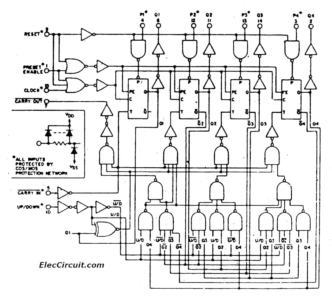
Universal digital counter circuit using CD4510 & CD4543
Asynchronous counter circuit design is based on the fact that each bit toggle happens at the same time that the preceding bit toggles from a "high" to a "low" (from 1 to 0).
LED Chaser Circuit Using 4017 Decade Counter DIY LED Chaser
LED Counter By hope0425 in Circuits LEDs 26,352 19 9 You can make an attractive LED counter that has various frequencies with a few simple electronic components. Ask Question Step 1: Place the Flasher IC Position the LM3909N IC about three rows of holes from the left side of the solderless breadboard assembly.

Buy Digital Counter Circuit 2 Digit LED 7 Segments Display [Unassembled Kit] Online at desertcartUAE
How it works The circuit may be easily divided into two sections as follows: Pulse Generator The counter and LED First, the pulse signal generator section includes IC1-NE555, R1, VR1, C1, and C2. The signal output from pin 3 will be in a square waveform, which frequencies can be adjusted by VR1.
Counter Display with LED 7 Segment Using CMOS IC
7-segment Display Counter Counters Tutorials Nowadays it is very easy to display numbers and letters across multiple LED displays using micro-controllers, such as the Arduino or Raspberry-Pi, along with a small bit of software related code to display the required digits.
Assembled Kit FA926 Digital Counter Circuit 2 Digit LED 7 Segments Display Shop at an Honest
The LED counter uses the configurable counter circuit and the configurable shift register created earlier. Using those two components I will build a circuit that cycles through the LEDs. Recall from the configurable shift register post that we needed a way to slow down the shift register so that the changes are slow enough for the human eye to see.
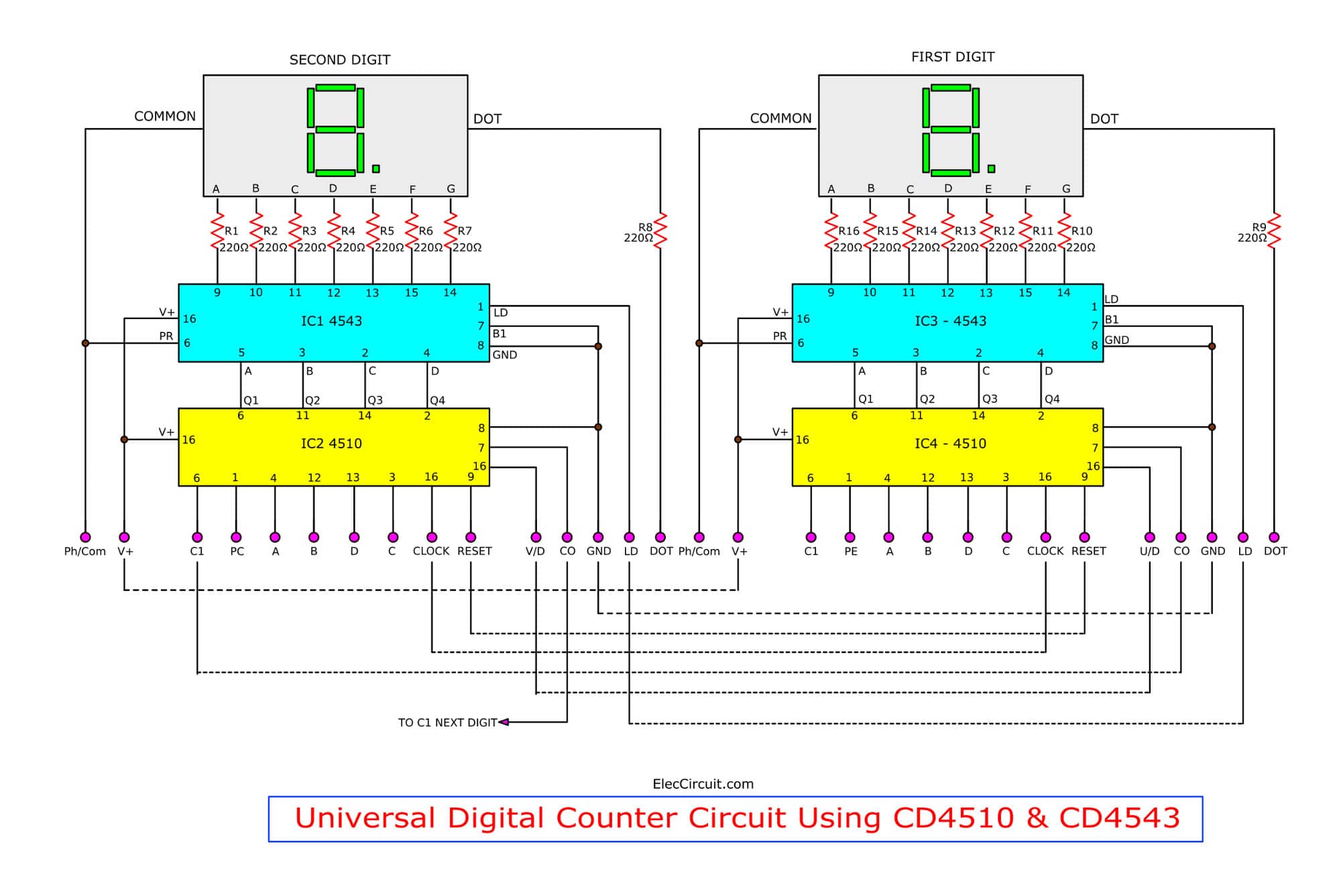
Universal digital counter circuit using CD4510 & CD4543
This document describes the construction of small frequency counter with a cheap PIC microcontroller and a few seven-segment LED digits. The main features of the frequency counter are: frequency range 1 Hz. 50 MHz (prototype worked up to 60 MHz but this exceeds the PIC's timing specifications)
7 Segment LED Counter Circuit With explanation Schematics, Circuits, Electronics design
Step 1: Connect the four switches to their pulldown resistors and the ABCD inputs of the 4511 IC, as illustrated on the left side of Figures 1 and 2. Figure 2. Breadboard implementation of the 7-segment LED display circuit. The BCD inputs are designated A, B, C, and D in order from least significant to most significant.
counter circuit Page 4 Meter Counter Circuits Next.gr
Top 20 of 2022: News reflects swings in LED application focus to counter supply and demand concerns Carrie Meadows Big players such as ams Osram, Lumileds, Cree LED, Signify, and GE Lighting continued to make moves designed to balance price pressures, supply-chain challenges, and shifting.